Automotive light measurement systems portfolio
Products > Automotive systems
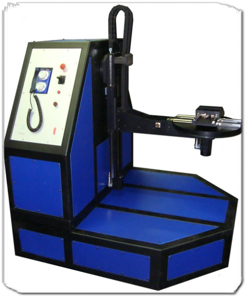
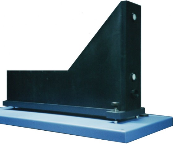
Goniometer
Goniometer Type A, as required from SAE J575 or IESNA norms.
Wide and stable base allows the operator moving around the goniometer on safety from axis movements.
Steel supporting framework. Testing device can throw of a maximum of 600mm from the table centre of rotation.
Wide and stable base allows the operator moving around the goniometer on safety from axis movements.
Steel supporting framework. Testing device can throw of a maximum of 600mm from the table centre of rotation.
The arm can move up-down with a motorised course of 500mm (proportional joystick control).
Manual X-Y horizontal movements over slides on rotary table allows movement range of ±150mm.
Centre of rotation alignment light for sample alignment.
Manual movements through hand wheels.
Power circuit for bulbs selection inside the arm.
Bulbs supply connector on arm near the rotary table.
Maximum supportable weight: 20Kg.
Features
of rotating table:
| of vertical rotation:
|
Working bench
Made combining a 19" rack with a wide table, allows to take place for the personal computer, monitor, printer.
Minimum characteristics of the supplied devices:
- Computer CPU Intel, 8GByte RAM, 500GByte SSDHD, Windows 10
- LCD TFT 22", Display 16:9
- Laser Colour printer A4 format.
- Rack containing the electronics, control instrumentation and user panel with touch panel control unit for instruments control and manual operations.
- Angled panel equipped with:
- key-switch on/off
- switch for bench lighting
- 2 switch for room lighting
- safety push button (it interrupts all motors and power supplies)
- internal control unit tft lcd touch panel.
- One or two power supply dual range (0-15V/7A or 0-30V/4A), and optional high power power supply (20V/38A): manual control or computer control. Computer control can produce blinking or PWM control.
- Electric chassis with differential main switch, lightning suppression and services.
- Desk light and swivel wheel chair.
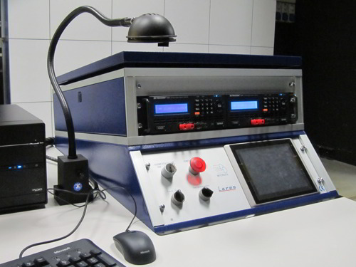
Currently, goniometer and work bench are produced exclusively for a selected clientele.
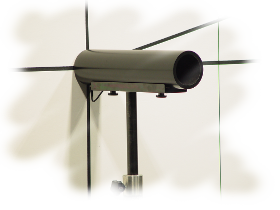
Photometric detector
- Spectral response following the CIE photopic action spectrum. This detector is designed to have a spectral response like that of the human eye’s visual response in the photopic region. Error V(λ)=1,5%.
- Wide dynamic range an excellent long term stability.
- Measurement on flashing light allowed.
- The photometric head is placed inside a stray light eliminating tube.
- Placed on a stable tripod with adjustment facility.
- Variable test distance possible ordering multiple tripod floor bases.
- The system can hold several luxmeters.
- The luxmeter case is fixed on the tripod base and connected to the bench trough a network cable.
- Software calibrated, no hardware trimming.
Reflex reflectors bench
Designed for laboratory space, it has been studied to operate at a distance of 15m in completely dark room.
Equipped with high sensitivity silicon illumination detectors with spectral response following the CIE photopic action spectrum. The choice of photometer heads is due to speed of execution of the measurements. The average noise in dark condition is about 1 mCd / Lux.
- Excellent long term stability, software calibrated, no hardware trimming.
- Light beam with uniformity error of about 6% open from 100mm to 260mm.
- Measure according ECE specifications: two photometer heads works contemporaneously at observation angles 20' and 1°30'.
- SAE measurement made at reduced distance (15m); two photometer heads works contemporaneously at observation angles 12' and 1°30'.
Measuring and processing software
All the system is computer based. Although you can manage some functions manually from the panel touch screen, for an efficient use of the benches it's necessary to use the measurement software.
Three kinds of multilingual software are presents:
Three kinds of multilingual software are presents:
Basic software
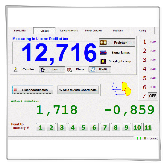
Residing into the internal control unit interface together benches, goniometer and luxmeters. Trough the touch panel shows luxmeters values, goniometer coordinates and system condition. Contains man machine interface.
Table management software
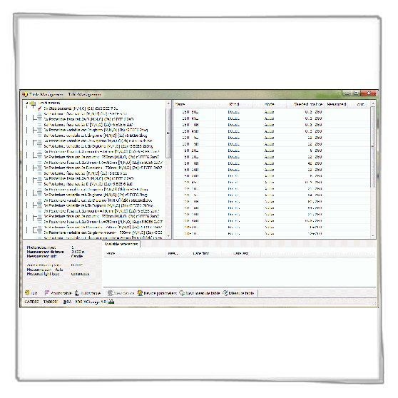
Windows software developed to make homologation measurements and check conformity of lamps to standards. Measures can be stored and elaborated in relations.
It's a table-structured system allowing the execution of measures on single points or zones and their comparison to required standards.
The operator can easy analyse measurements archives and covert groups of these into Excel files ready to print a report. (Require Microsoft Excel installed on the system).
This software is constantly upgraded to meet new ECE norms requirements.
Maps management software
It is a complete system for the analysis and development of lamps optical geometry.
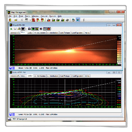
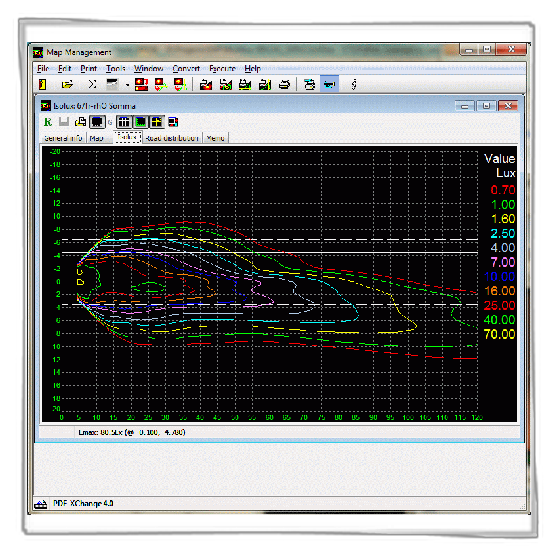
Allows visualising on the video: brightness maps, isolux (isocandle) curves and distribution curves. All printable through the window interfaced printer. The different possible window rooms give the possibility to compare simultaneously different measurements.
Maps management software supplies the following collection and management of:
1. Brightness map 2. Isolux and isocandle curves
3. Distribution curves 4. Sum of maps
5. Map conversions (from vertical to horizontal, from vertical to distributions)
6. Cutoff line position and sharpness.
Illumination of rear registration plates measuring
ECE Regulation n°4 measurement
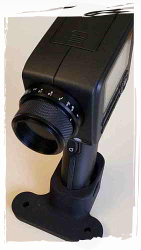
The developed system uses the Konica Minolta LS-160 luminance meter.
To measure, place the meter on the goniometer table by means of a suitable fixing (bottom of the image), the plate must be placed in front above a stand that is 4297mm from the center of rotation of the goniometer and which places the plate at this height. The license plate lights must be connected to a power supply and powered as necessary. The alignment is checked and the measurement is started.
A dedicated software allows automatic measurement, storage of measurements and printing of a report.
Afterwards it is possible to view and print the stored measurements.
FMBSS108 License plate lamp photometry
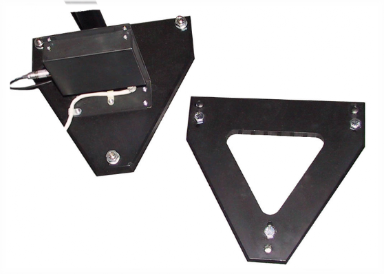
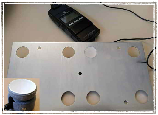
As required by the legislation, the illuminance is measured at different points on the plate. A 1.5mm thick perforated steel plate is supplied with the dimensions of a US automobile license plate; the holes are suitable to house the photocell in the measurement points required by the regulation, see image:
The measurement takes place manually, guided by the program, the photocell support is inserted in the indicated seats and is measured. At the end of this operation the result is processed by the program following the indications of the regulation expressed in paragraph FMVSS108 S7.7.13 Photometry.
Short distance reflex reflectors bench
Vertical version
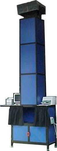
The system performs measurements at a distance of 3m and is built to around the need of reflex reflectors photometric measurements outside dark room. This distance of measurement requires the use of very small photometric elements, with a large error on the measure on the spectral response of the human eye. The drawback, however, is eliminated with a color correction table in the measurement software. The system allows fast measurements through the use of photometric elements placed at observation angles in accordance with ECE and FMVSS108 standards. This system does not allow the movement of the reflex reflector, the measurement is performed with a fixed angle of incidence. The projector provides a constant light beam through its controlled supply.
On the bench can be placed a notebook. A dedicated program guide the operator to perform and store the measurements in database. Database measurements can be printed.
The projector is placed at the top of the cabin. This has dimensions of about 120l x 60d x 500h cm, built with aluminum and plastic enclosures panels. The system is mounted vertically with the projector at the top. On the operational side, the measurement area is obscured by a black cloth curtain. Computeris housed at the height of 130cm on a small shelf, there is also space for an optional printer.
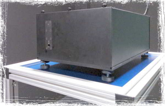
Horizontal version
The system performs measurements at a distance of 3m and is built to around the need of reflex reflectors photometric measurements in small size. Measurement must be executed in darkroom. This distance of measurement requires the use of very small photometric elements, with a large error on the measure on the spectral response of the human eye. The drawback, however, is eliminated with a color correction table in the measurement software. The system allows fast measurements through the use of three photometric elements placed at observation angles in accordance with ECE and FMVSS108 standards. This system does allow the movement of the reflex reflector sample trough the use of a manual goniometer that allows to change the incidence angle. The projector, placed on a special table, provides via its power supply checked out a beam of light with constant constant intensity.

